Learning Houdini: Post-Course, Thoughts and Creating Tools

Making Of / 08 October 2019

This post was originally written on September 20, 2018

Background, in 2018, I did a Houdini certification at NYP in Singapore.


Houdini Course

Last Assignment

A year ago, I completed my Houdini class. My last assignment was part of the VEX module and it’s probably the chapter that scared me the most and ended up enjoying a lot. There was a lot of “Ah ha” moments and it was really satisfying to finally be able to accomplish anything trough code and understanding it. 

The final assignment brief tasked us with the following tasks:

1.    Starting from the given MeteorCrash_start.hipnc file.

2.    Using Houdini, fracture the meteor so that even the inside of the meteor contains small pieces.

3.    Writing VEX code (through Attribute Wrangle node) to drive the meteor planet crashing effects, so that the core crashing effects are deterministic (not through any form of simulations).

4.    In the VEX code, vector dot product function must be used to detect the penetration between the meteor and the planet. And vector cross product function must also be used to determine the spreading directions of the shattering pieces of the meteor.

5.    Transfer attributes from the force field to the meteor to drive features of the meteor pieces (like color for example)

6.    Flipbook at least 100 frames to show the whole process of the meteor crashing into the planet (starting from a whole meteor).

7.    BONUS: adding extra particle effects to the crashing effects to make it more impactful. Simulations (through SOP Solvers or DOP Networks) can be used to create the particle effects.


Above is the whole network I did for creating the system above. The code is stored in the attribute wrangle nodes in purple.

  • The meteor breakage was done using the same techniques used for the house explosion simulation.

  • Using vex, I was able to drive the disintegration of the meteor proportional to its distance from the planet. 

//Fetch data 
int nearPoint = nearpoint (1, v@P);
vector nearPos = point (1, "P", nearPoint);
vector nearNormal = point (1, "N", nearPoint);
float distance = length (nearPos - v@P);
vector diff = nearPos - v@P; 

//dot product 
float dot = dot (normalize(nearNormal), normalize(diff)); 
//set group 
if (dot > 0) {
        setpointgroup(0, "insideForceField", i@ptnum, 1, "set");
 }
 
if (distance < 0.1) {
    setpointgroup(0, "impacted", i@ptnum, 1, "set");
 }

//cross product
vector cross = normalize(cross(nearNormal, diff)); 

//strenght of spreading of meteor pieces 
float spread = fit(distance, 0, 0.2, 1, 0) * chf("impactForce"); 
vector impact = cross * spread;
 
//applying impact force 
v@P += impac
  • I set up groups to delete some parts once they were passed a certain distance and to transfer the color attribute of the planet atmosphere on the selected impacted pieces.

So far, all of it was deterministic. The debris are, however, a simulation because we need information from previous frame to calculate what is coming, which requires a solver sop. 

  • The simulation was setup with an initial velocity.

  • Inside the solver, we used the velocity to move the particles.

v@P += v@velocity;
  • Then, I had to create the force to drive the attraction of the particles to the planet’s force field and also the force to repel them from it.

Attract

I set the particles to be attracted to the centroid of the force field. Using a cross product, I am able to make them rotate toward that center point.

//Fetch Data 
vector normalizedVelocity = normalize(v@velocity);
vector normalizedDifference = normalize(chv ("forceFieldCentroid") - v@P); 

//Cross product 
vector cross = normalize(cross(normalizedVelocity, normalizedDifference)); 
//apply rotation 
vector4 myRotation = quaternion(0.5, cross); 
v@velocity = qrotate(myRotation, v@velocity);

Repel

The particles are rotated away from the nearest point on the force field proportionaly to the distance between them and the force field. Similarly to the attract portion, the repel portion uses a cross product to rotate the particle away. To drive the intensity of the rotation base on the distance between the particles and the nearest point on the force field, I am using a fit function like the dissolving meteor.

//fetch data 
int nearPoint = nearpoint (1, v@P); 
vector nearPos = point (1, "P", nearPoint); 
vector nearNormal = point (1, "N", nearPoint); 
vector diff = nearPos - v@P; 
float distance = length(diff); 

//cross product to get the axis of rotation 
vector cross = normalize(cross(v@velocity, nearNormal)); 

//strenght of rotation we want to apply 
float angle = fit(distance, 0, 0.5, 1, 0) * chf("rotationIntensity"); 

//apply rotation 
vector4 myQuat = quaternion(angle,cross); v@velocity = qrotate(myQuat, v@velocity);

In the future, I would like to improved the motion of those particles as their spreading motion is happening quite slowly and is a little bit awkward.

Post-Class

The class gave me a good foundations where I explored all the big features of Houdini and I build upon those to continually improve. It allowed me to be fluent enough so I can watch webinars, tutorials and talks with more ease. But I am also aware that I barely scratched the surface of what Houdini can do, and more broadly, the possibilities and potential of having a procedural art pipeline.

The full course is composed of two parts: the classes and a project module. I won’t be doing the project module but I still would like to do some projects and tools of my own. So I am currently brainstorming and researching what kind of tool I would like to develop. It is also a way to stay updated and keep all of what I’ve learned fresh as it’s so easy to forget things when you don’t practice.

Small Tools

I created a tool for generating a golden spiral and another one to visualize the superformula. They are not converted into a digital asset yet as I am not done with the UI, but this will be the next step.


Learning Houdini: Flipper Game

Making Of / 08 October 2019

This post was originally writtenon July 2018

Background, in 2018, I did a Houdini certification at NYP in Singapore.

The assignment brief:

Flipper is a game character that has been animated to move in a circular path, along the ground which is colored in patches of red and blue

Part1 
 Much like in a computer game, as Flipper moves along the ground and touches the RED areas, he will score points in the form of coins or balls that will emit from the contact areas. These coins will bounce a few times and settle on the ground.

Part 2
 As Flipper returns the second time, he will ‘collect’ these coins.  The coins will be ‘sucked’ into him when he comes near them.

Bonus :  Much like a game, display the number of coins collected at the top right of your camera. Use the font SOP to create this.    

The simulation is divided in two parts. The challenge in part 1 was how to detect the red zone and only emit from those points when Flipper passes over them. They are multiple ways to approach the problem, but one of the simplest solution was:

  • Get the intersection between the rubber toy and the ground.

  • Add some thickness and scatter points along the intersection.

  • Transfer the color attributes from the ground to the points. 

  • Delete any points that are not red.

  • The remaining points would then be the emitters.

Transitioning between part 1 and part 2 was another challenge. You want to stop Flipper emitting particles before he starts attracting them and you don’t want it to suck back the particles as soon as they were emitted. I ended up going with a “hard coded” solution instead of having a fully procedural one so there is room for improvement.

  • I ended up deleting the emitter points at frame 71 when Flipper is done doing its first lap.

  • Because the particles network (Popnet) still exist, the already emitted particles stay there.


The second part involve creating a force that would push the particles to Flipper when it is close to them. This part was probably the easiest one to do but keeping good controls over the simulation was a little bit tricky. We first need to create the suction force.

  • To get the suction force, we need to calculate the distance between a particle and Flipper. 

Then, we need to establish the conditions for when the suction is applied.

  • The distance between Flipper and the particles needs to be under a certain number.

  • The frame should be past 71 (when Flipper is done emitting).

Finally, we need to set what happens to the particles when they are sucked back to Flipper. My first reflex was to kill the particles when the distance between Flipper and the particle is below a certain number, but because we want to keep track of the score, we cannot kill them inside the simulation. Instead, I am using a collision detection node. 

  • With the particle collision detect node, I can keep track of the particles that were absorbed by Flipper, but I can also group them. 

  • Outside the simulation, you can then delete the group so they don’t stay visible. 

  • With a Font node, you can then read the collision number to show the score.

I replaced the particles by coins to add context to the simulation. The coins were also falling without rotating because their orientation follows their normals. I used their velocity as their normals instead so they can fall in a more natural way.

Houdini: Bridge Generator

Work In Progress / 30 September 2019

Note: This post was originally written on September 26th 2019.

Today, I started working on a tool to generate bridges. I went with a simple rope suspended bridge, the kind that we could find in an action adventure game on a remote island. 

The goals were:

  • Be able to control the length, height and width of the bridge

  • Be able to control the bending of the bridge

  • Be able to control the elevation of the bridge

I was able to do the basic logic of the bridge generator, but a lot is still missing. The process went relatively well. What I learned doing my fence tool was very useful in this one too. Unfortunately, I had to redo it twice because Houdini crashed and I didn’t save my work properly. Lesson learnt (until the next time ^_^;).

What I want to improve:

  • Currently, the planks do no follow the orientation of the side cables. It doesn’t look too bad when the bending angle is small, but when the bridge is very bent, it’s quite obvious. To fix this, I think I need to generate the normals for each point on my lines and use that normal to influence the rotation of the planks.

  • The general look of the bridge also needs to be improved. A lot of details are still missing as well as controls. At the moment, the grounding cables and poles aren’t easily modifiable. The knots are just sphere. I would also like to be able to generate random cracks on the planks, maybe add the possibility to have broken ones. I would like to add the support to replace the meshes with production quality meshes.

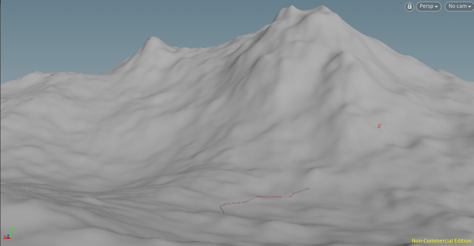
  • I would also like to add a terrain and see how the tools can be improved when used in a more realistic context.

Book Generator in Houdini

Work In Progress / 30 September 2019

Note: This post was originally written on July 24th 2019.

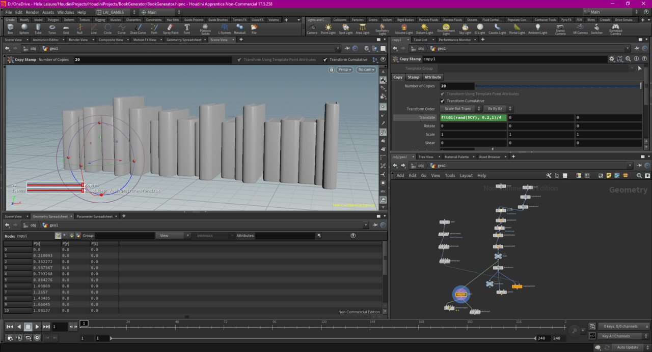
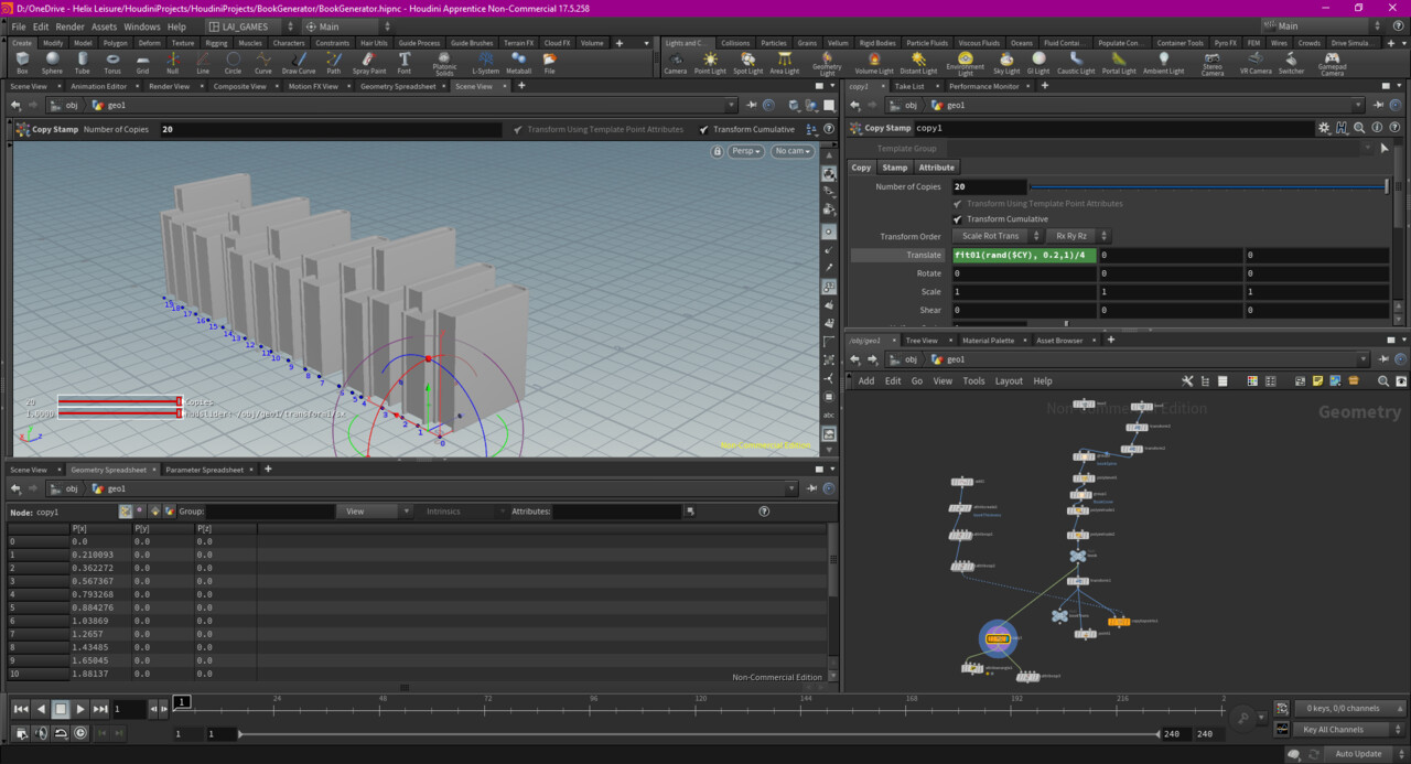
Today, I tried to make a book generator in Houdini. It didn’t go as planned. 

What I wanted to do:

  • Be able to generate X amount of book

  • The books should have various width and height

  • The book should have some variation in their alignment

  • The book should first be generated next to each others

  • If I have time, the books could have different rotation angles

So I managed to have random outputs of books. But I encountered a major challenge (for me at least) where I struggle to find how to achieve what I want. The books should be placed at the end of the previous one. The problem is I am only able to translate with a global number and not based on the bounding box of the previous book. I am pretty sure the solution is something like the following:

  • For each book, retrieve the bounding box in X axis and that to its translation.

However, I am not sure how to make the copy stamp work with the wrangle node.

It’s disappointing, but I’ll continue to think about it and see how I can address this issue. 


Houdini: Improving Fencing Tool

Work In Progress / 30 September 2019

Note: This post was originally written on June 27th 2019.

For this Personal Development time at work, I wanted to improve the fencing tool I started working on last month. It didn’t really change visually unfortunately, but the system itself is more robust and flexible.

  • Fix input system

    • Can now use both curve tool and draw curve input

    • Work with closed curve

  • Added better interface control

    • Can switch between fence tool and other types of inputs

    • Added curved control

  • Can switch between heightfields and curves will adjust themselves to the new terrain

Fix Input System

Previously, editing the curve wasn’t convenient as it was then position with a transform node. I modified that in order to adjust the curve and be able to see the curve being projected right underneath on the terrain.

Can now use both curve tool and draw curve input

I also added another input method. It is now possible to draw the curve on the heightfield. It made the generation very quick and easy, but it’s less precise than the curve tool.

Work with closed curve

By fixing the input system, it now supports open and close curves.

Added better interface control

I added a lot of controls trough a UI panel. The goal is to allow the end user to be able to create what they need from this control panel. 

Can switch between fence tool and other types of inputs

You can now switch between the fence generation tool and any input mesh of your choice. In the example above, I used a test mesh provided by Houdini. 

Added curved control

I also added control over the orientation of that mesh. It can follow the orientation of the curve or follow the world orientation. I also added control over the actual rotation of the object.

Can switch between heightfields and curves will adjust themselves to the new terrain

The images above shows the same curve with two different heightfield. I was able to achieve this by fixing the settings of the raycasting node for the curve tool and by projecting the drawn curve onto the terrain. This adds a lot of flexibility to the tool as it means it can adapt to any changes in the terrain.

Future Improvement and Next Projects

At this point, I simple need more assets to play with. The system is now flexible enough to accommodate a lot of meshes and situations. The last step at this point would be to convert that into a HDA and see how easy it is to use in another project. Exploring more possible usages will influence what features should be added. I will definitely revisit this tool when I have more projects and assets done.

Next, I am tossing between developing a basic biome system or a book generator. The book generator might be a little bit easier to do than doing a biome, but both could be great tools to have to facilitate level art.

Houdini: Creating a Fencing Tool

Work In Progress / 30 September 2019

Note: This post was originally written on May 22th 2019

It has been a few months since the did a project on Houdini. I wanted to go back to it so I do not loose the skills I have and also to improve what I already have. I decided to create a fencing tool since it’s a good starting point and actually a very versatile tool that could help us build levels faster (more on that at the end of the post).

Today’s Goals

  • I wanted to be able to draw a curve and generate a fence from it

  • I wanted the curve to conform to a terrain

  • I wanted to be able to control the fence appearance

What I Did

To achieve this, I had to design two different systems:

  • One to create a portion of the fence itself with a control panel that would later be used for controlling the digital asset.

  • Another one to draw a curve and generate the fence from it.

During today’s Personal Development Time, I was able to create both system, however, I didn’t have time to make the fence look appealing with many controls over its appearance.

I faced some challenge over the control of the normals and the fence orientation when ray casting it to the heightfield. Also, the ray casting created a very noisy result at first, so I had to change my approach to keep the input as simple as possible to make sure it was as clean as possible.

Future Improvement

  • I want to create a great digital asset for fence generation with multiple fence styles and controls

  • I want to add randomization of instances when generating the fence so not all sections look the same

  • I also want to see how I can include texture automation and see if I can integrate substance designer

  • I would like to make it compatible with close curve system and open ones (currently works with open)

Future Usage

This tool is the base of many other potential tools:

  • Replacing the fence with shelves and we can create the interior of shops and libraries very quickly

  • Replacing the mesh with lamppost and we can quickly dress the side of a road

  • Replace the fence mesh with houses and we can easily create streets and neighborhoods

  • This will need more work but I believe I can create from this tool a bridge system

Substance Designer: Finishing Sci-Fi Grid

Work In Progress / 30 September 2019

Note: This post was originally written on April 29th 2019

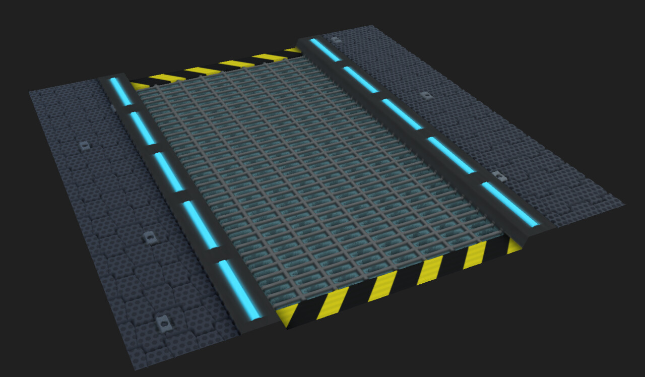
As part of my goals, I wanted to finish the sci-fi substance this month. I ended my last blog post mentioning the improvements I wanted to do on the sci-fi grid.  

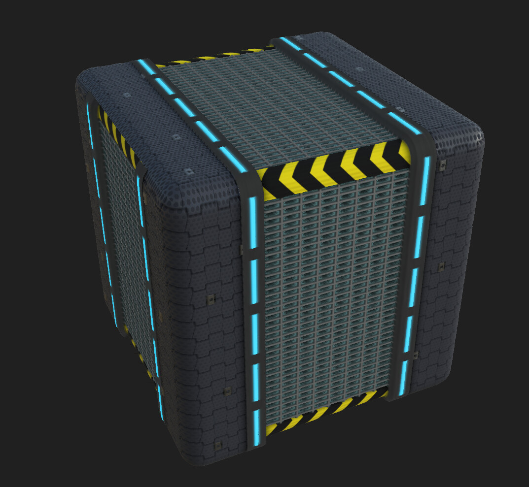
Finishing Touches

During lunch time, I was able to add:

  • Damage to the chevron pattern

    • Making the metal peak through and adjust the roughness so the pattern doesn’t have the same level of roughness than the metal underneath

  • Dirt concentrated between the tiles on the sidewalk

  • Rust on the grid

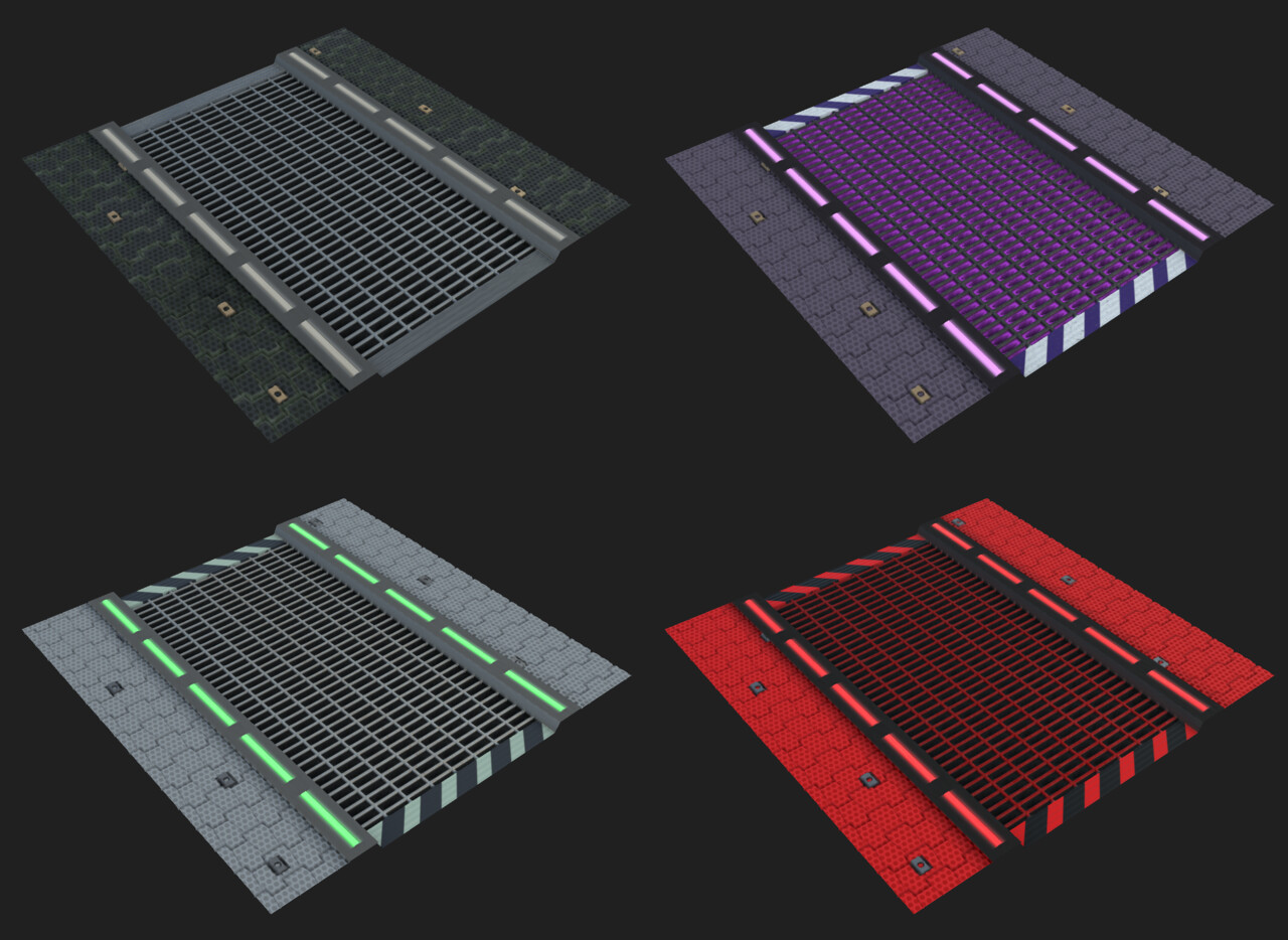
  • Expose parameters and give the end user control over the colour palette and the amount of dirt and damage.

  • Include multiple details in the roughness map

Some variation. It’s not as diverse as the pebbled forest ground because a lot of the elements need a specific scale to tile properly. I tested a few things and my masks all update appropriately if I change the scale of certain elements, but it would require a little bit more work to control the range of change and ensure the material always looks okay.

Final Thoughts

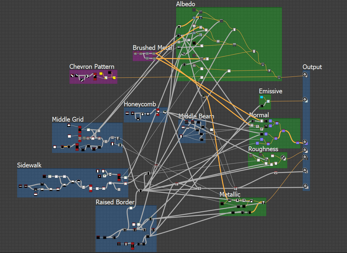
It was a really fun substance to do and probably the most complex one I’ve done so far. Well planning the substance and the mask really helped creating the various maps. For the future, I would like to see how I can make a complex substance like this even more versatile by giving more controls to the end user. 

Sci-Fi Grid in Substance Designer

Work In Progress / 30 September 2019

Note: This post was originally written on April 24th 2019.

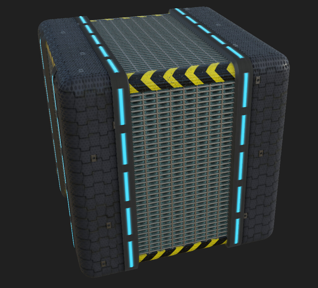
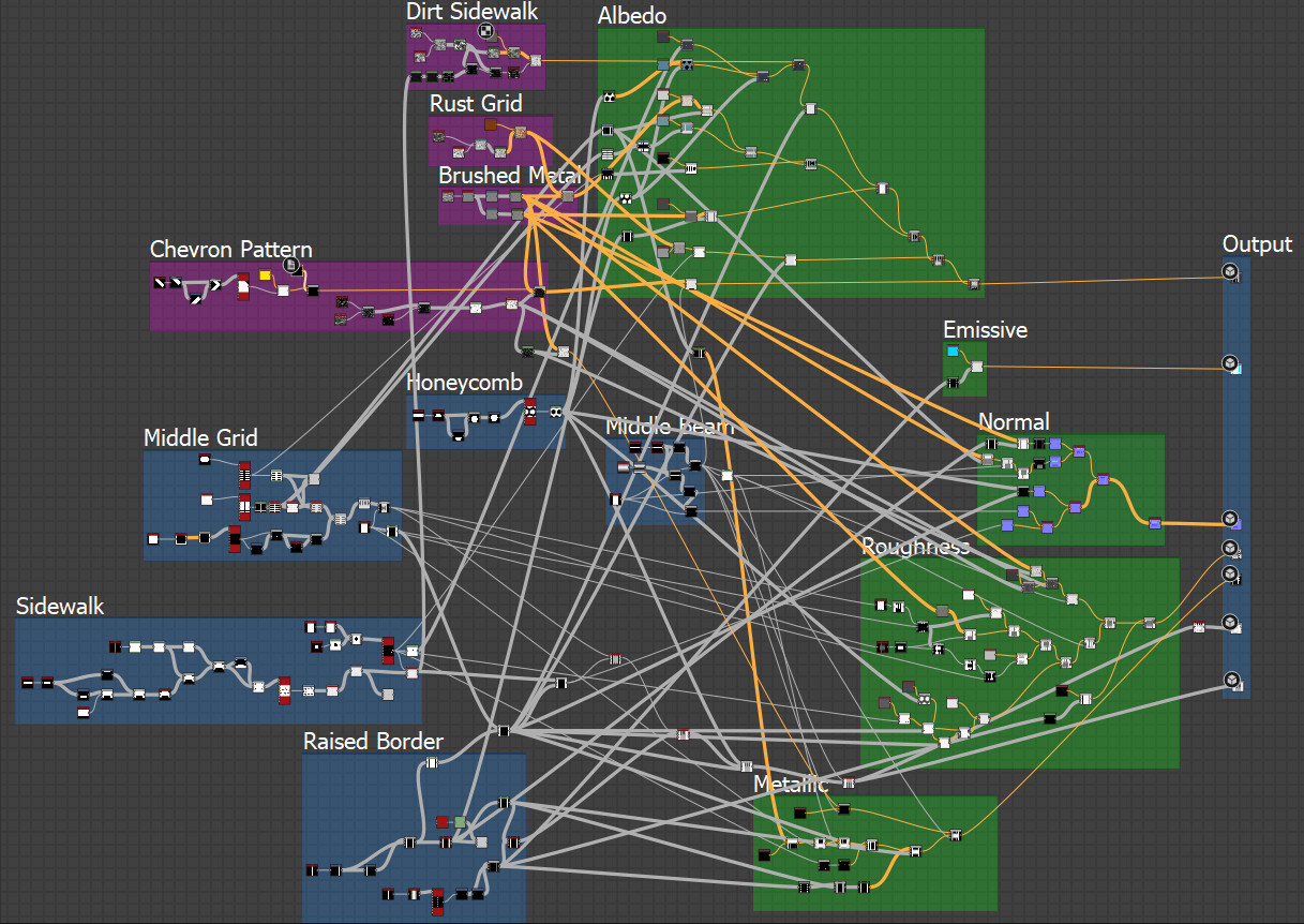
Today, I started working on a sci-fi material. Sci-fi isn’t my strongest suit, but I wanted to try to create something more structured compare to the previous two substances I did. Overall it went very well and I was able to control all the elements very easily and didn’t struggle to create the patterns I wanted. I think I improved drastically from my first wood substance I did couple months ago. 

What was done

Using the new techniques I learned from watching Allegorithmic’s webinar with Javier Perez, I was able to control my height maps and how every elements layered on top of each others.

I was able to reach a level close to completion for:

  • Height map

  • Albedo

  • Emissive

  • Metallic

  • Ambient Occlusion


I still want to perfect the normal map and roughness.


For Next Time

I want to add some damage and add colour controls for the end user. I don’t think I will give a ton of controls over many elements as this design doesn’t fit this too much.

Continuing Substance Designer Forest Pebble Ground

Work In Progress / 30 September 2019

Note: This post was original written on March 26th 2019.

Progress

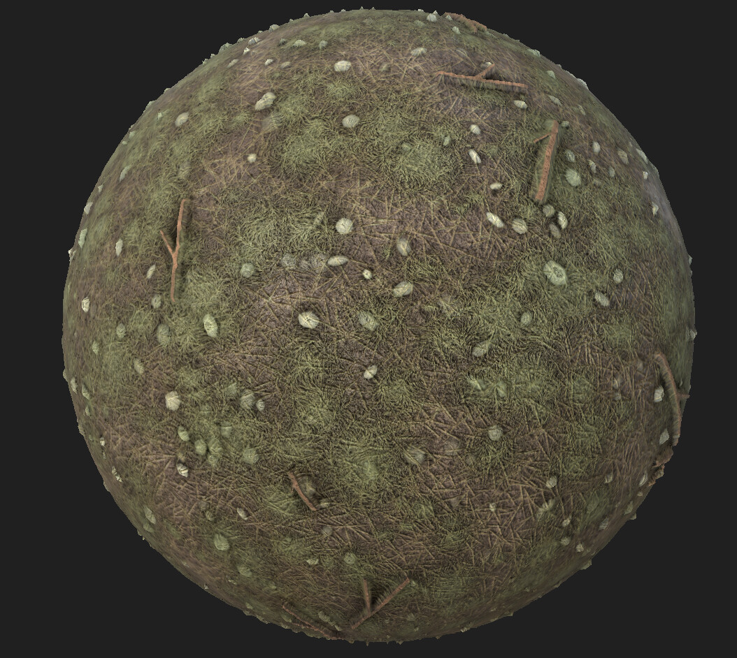
Last Personal Development time at work, I started working on this new material. This time, I was able to advance it to a satisfactory level where I am ready to start working on a new one.

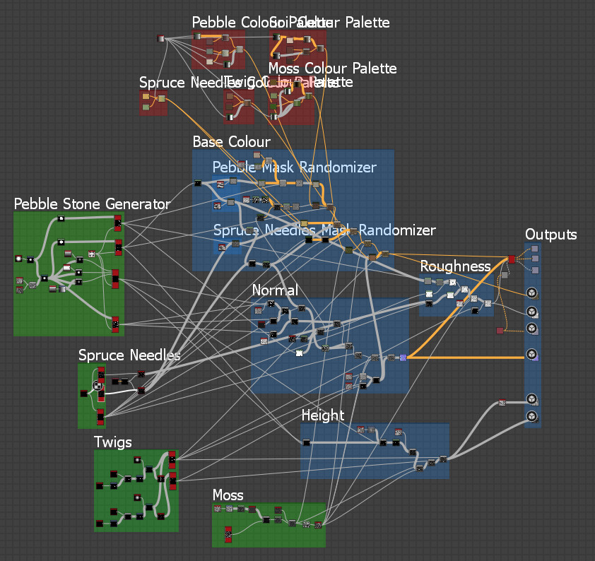
  • Cleaned up graph

    • Added boxes to help navigating trough the graph

  • Added moss

  • Made output for both PBR (spec/metalness) and non PBR (specular/gloss) workflow

    • The material was initially done for PBR. When studying Mark Foreman’s medieval tudor bricks, I saw that Substance Designer have an output converter to transform output maps to non PBR. This is very practical as it allows to make the material even more flexible by being compatible with both pipelines.

  • Added colour palette control

    • Based on Mark Foreman technique, I added colour palette controls for each elements so it’s easier to tweak the colours and more colour varieties are now possible in the base colour map.

  • Exposed parameters

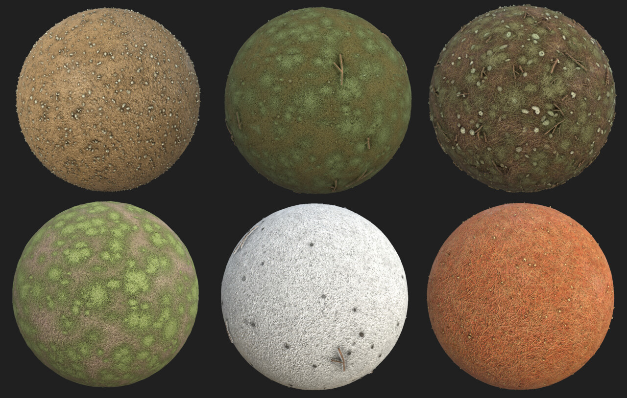
    • I exposed all the parameters needed to control the look of this material, from the size of the pebbles to the spread of the moss.

Below are a few examples of how the material can be adjusted with the exposed parameters.

Final Thoughts

It was a very fun project and I feel that the quality of this substance has drastically improved compare to my first attempt (the wood). I was able to put into practice what I learned from Mark Foreman’s webinar and all those new techniques allowed me to better control my material and make it more flexible. There is a new webinar available from Allegorithmic with Javier Perez showing how he did one of his sci-fi material. I am looking forward to see what new techniques and approaches I will learn and how I can apply them when creating my new substance material.

Substance in Unity and Starting a New Substance

Work In Progress / 30 September 2019

Note: This post was originally written on February 28th 2019

Some more details

At first I wanted to test my wood substance in Unity right away, but I got a little carried away by adding a few more details: long cracks and knots. Both of them are created with the shape nodes which I never used before but I definitely want to play more with it as it allows you create any shapes you want. It is a very powerful node.

Long Cracks

  • I blended a few thorn shapes that were distorted by a directional wrap. 

  • Using transform 2D, I offseted the shapes so their placement would be appealing.

  • I then tiled them across the surface.

Knots

  • By blending multiple disk shape of various size, I was able to create a ripple shape.

  •  I added some distortion with the direction wrap

  • I created a splatter effect to disperse it on the wood texture. 

Input Parameters

By adding those two details, I had to adjust the input parameters so the intensity can be adjusted by the end user. 


Using Substances in Unity

Asset Store

Substance isn’t integrated natively in Unity anymore as Unity decided recently to not have any third party system on a native level. You now need to install an external package from the asset store. It is pretty straight forward but reviews shows that the change from being natively implemented to being a package has created problems for a lot of users.

Import

Substance Designer standard files that contains the full graph are .SBS files. To use substances in Unity, you need to publish your substance as a .SBAR file. Once published as a .SBAR file, you can easily add it to a Unity project. 

Inside Unity

Inside Unity, you get the following:

It automatically creates a material that can be used on any mesh. The graph object is where you access the exposed parameters. You used to have to bake the substance but it seems now that every changes made to parameters will rebake the maps used in the material. 

Something else I noticed was the normal map. It looks yellow, which is obviously a sign that something is wrong with the normal (it should be blue/periwinkle). After some research, it seems to be a consequence from switching to a package instead of being natively supported. Unity simply doesn’t recognize the map as a normal map but the output in the editor looks okay, which suggest some magic under the hood is happening to still make it work.

I was also curious to see the difference in renders between Unity and Substance Designer but it looks quite good. Because I designed this subtance to output a specular map, I switched the shader to Standard Specular, but substances are compatible with Unity’s standard shader as well as Standard Roughness.


Multiple Instances

It is quite easy to create multiple versions of a material. In this example, the Wood.sbsar object allows you to add instances of a material. Now you are free to apply them to different objects, adjust the material independently from the first instance and bake the maps.


Improvements

As with many things, there are multiple ways to approach the creation of wooden planks in Subtance Designer. The way I did it doesn’t give me enough control over each plank so having variety and unique details for each of them wasn’t easily doable. I think I need to plan better masks for the future. 

New Substance: Forest Pebble Ground

I wanted to play with the shape node and the tile sampler node and decided to create a pebble ground. This time around, I am way more familiar with the nodes and I was able to be much quicker compare to the wooden planks substance. I created this one during the afternoon.

I also took some advices from the monthly webinar I watched from Allegorithmic (write up coming soon!) in order to add some “randomness” to it. 

My main approach was to create the shapes for each elements then tiles them. Some elements have multiple tile texture like the pebble stone because I needed different type of masks (grayscale variation, soft gradient, hard edges, etc). After that, it was just a matter of blending the right masks together and extract the right data.I didn’t have time to properly expose all the parameters for controlling the material. At the moment, only the amount and size of the pebbles are controllable.


I decided to import to unity quickly at the end. It is the first time I’m working with height maps so I was curious to see how it would look. 


Improvements

I would like to add some leaves, grass and moss. I also need to properly expose the parameters so every elements can be adjusted.